Fundamentals of Forming Limit Curves (FLC) Testing

The automotive industry is providing us with more and better vehicles,
but we may never have given much thought to how such amazing machines
are created. Any vehicle has numerous components, with the body
structure being the most important. Most automotive bodywork is made
of steel and aluminum, particularly in the form of thin sheets. Those
sheets are formed into certain car body parts by the Stamping Process;
a process in which sheet metal is pressed between a pair of dies with
a specific shape, forcing it to conform to that same shape.
Since this process involves plastic deformation, the metal part will
remain in the desired shape even after the stamping is completed. When
designing the stamping process for any given part, many parameters
should be considered. Designers and manufacturers should have a
reliable prediction for material behavior under a certain amount of
press load, and for a specific die shape, to successfully fabricate
the part. They simply need to know the limits by which a sheet
material can be stretched before failing, or in other words, its
“Formability”. We will explore the basics of formability testing,
including theory, equipment, methods, results, and testing standards.
Definition: What is Sheet Formability?
Sheet Formability refers to the ability of a sheet metal to be
formed into the desired shape without cracking or rupturing. For
the simplest explanation, the tension test will be taken as an
example.
In this test, a dogbone-shaped test sample undergoes a tensile
load along its axis until rupture; from force and elongation
measurements, the well-known “stress/strain” curve can be
constructed. The x-axis here is strain, and it represents the
change in length with respect to the original length of the
dogbone sample (e=∆L/L0).
Formability in this case is equivalent to the “ductility” of the
material; the latter can be arbitrarily taken at the point of
necking (uniform ductility) or at point of rupture (total
ductility), or somewhere in between.

FLC Testing at FADI-AMT
When moving from the simple tension test to actual sheet metal
forming operations (such as the stamping of a door), the
deformation of the material becomes more complicated, simply
because the material is deformed in two directions at the same
time.
Nevertheless, the definition of formability is similar yet
scalable to this more complex case; i.e., sheet formability is a
measure of the ductility of the material when deformed in two
directions. If we take any particular small region within a
stamped door, we will notice that the material is
stretched/compressed in two directions by different amounts to
generate the features and complex details of the door. If we were
to measure the amount of stretching in the two directions, then
the ratio between the smaller amount (minor strain) and the larger
amount (major strain) is known as the “biaxial ratio”; determining
the ductility limits of the material for various biaxial strain
ratios is accomplished by “sheet formability testing”.

FLC Testing at FADI-AMT
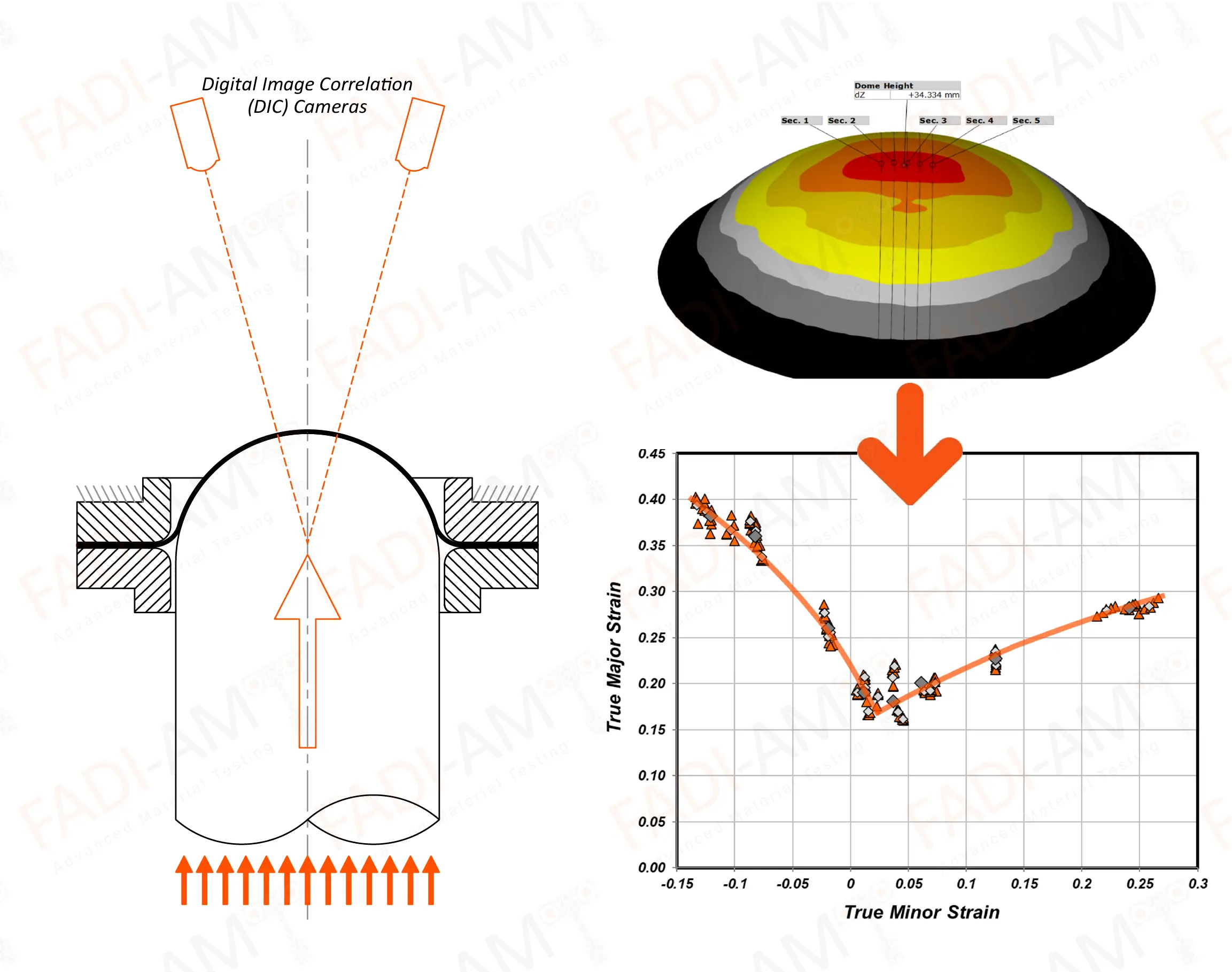
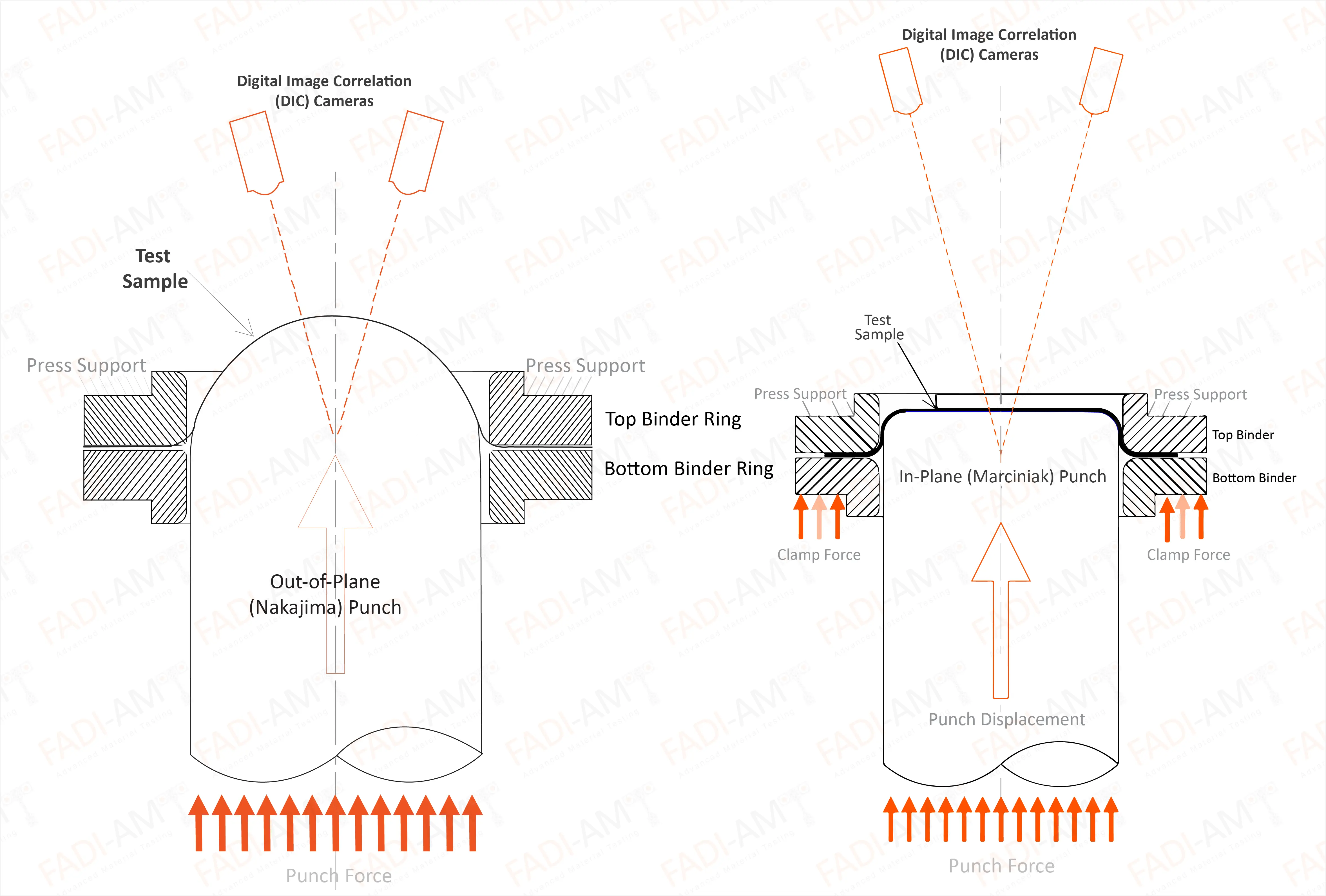
In sheet formability testing, a test sample with a particular
geometry is clamped firmly between two binder rings and an
axisymmetric punch (hemispherical or flat) is then driven against
the test sample deforming it until rupture. The test sample geometry
is designed intentionally to have a varying aspect ratio in order to
induce different biaxial strain ratios.

FLC Testing at FADI-AMT
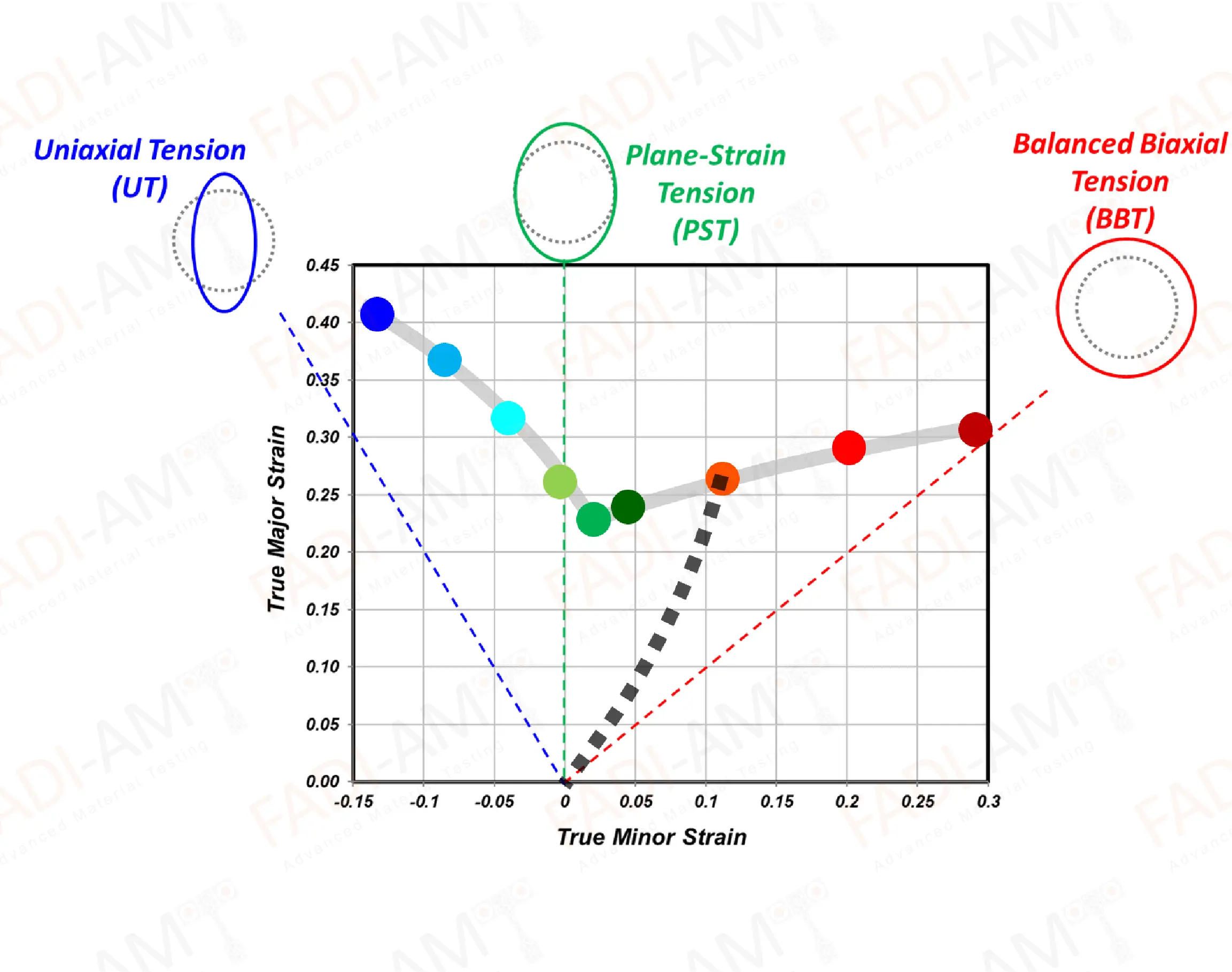
There are three main critical strain ratios (or loading paths)
that are relevant to sheet formability testing: Uniaxial Tension
(UT), Plane-Strain Tension (PST), and Balanced Biaxial Tension
(BBT). Each one is characterized by different strain ratios.
Uniaxial Tension (UT) describes a situation where stress is
applied entirely along the major axis with no loading in the
transverse direction. However, the since the material is
stretching along the major axis, it must also contract along the
minor axis to maintain a constant volume. This leads to a typical
UT strain ratio of -0.5 (the strain ratio is negative because the
minor strain is compressive).
Plane-Strain Tension (PST) describes a situation where
there is stretching in just the longitudinal direction without any
change in the width, thus producing a strain ratio close to 0.
Balanced Biaxial Tension (BBT) describes an extreme
situation where there is an even stretching in both the
longitudinal and transverse directions, thus implying a strain
ratio close to 1.

Test samples are designed to achieve these three main strain ratios,
as well other ratios in between these critical values; this way one
can guarantee coverage of the majority of strain ratios encountered
during sheet metal forming operations. During testing of any
particular sample, the minor and major strains accumulated as the
material deforms are tracked and measured; the values corresponding
to an “arbitrary” point of instability are then recorded. This is
performed for each sample geometry, with at least three repeats per
geometry for statistical reliability. By connecting all the recorded
instability points, a “Forming Limit Curve” (“FLC”) takes shape.
This FLC, typically a V-shaped curve, provides a general map for the
formability of the material; any combination of minor/major strain
accumulations higher than those described by the FLC curve are
likely to lead to material failure, while combinations falling below
the FLC curve are likely to lead to successful forming. Since
necking is not easy to determine during biaxial stretching, the
“instability” point at which an FLC point is taken during the test
is arbitrary, and it is typically based on complex algorithms in
order to lead to a state somewhere between necking and rupture.
This video shows a 3D demo of the Formability Testing Method
FLC Testing Equipment
Based on the principles described before, formability testing
requires two fundamental forces: a clamping force to hold the test
sample in place, and a punch force that is responsible for
deforming the test sample to failure. Any test machine capable of
producing these two forces independently can be used. There are
several ways available to achieve this, but typically a
dual-acting hydraulic press with custom tooling is the most
appropriate means.
There are even specialized hydraulically-powered machines, known
as “Universal Formability Testers” (UFT), that have been built for
this purpose, and they are simply compact self-contained presses
designed specifically for formability testing.
In terms of sensors, the most important type needed for FLC
testing is a biaxial strain sensor. As the test sample stretches,
the strain sensor measures the major and minor strain
accumulations across the sample. With the latest developments in
FLC testing, and the need for complex algorithms to determine FLC
points, optical metrology sensors using digital image correlation
(DIC) are now the only practical means for satisfying the
requirements of FLC testing.

Universal Formability Tester at FADI-AMT
FLC Test Sample Geometry
This image below shows different geometries used for the Formability
Testing.

FLC Test sample geometries at FADI-AMT
FLC Testing Method
This video shows the actual method of the FLC testing at FADI-AMT
lab
FLC Testing Results
The FLC is one of the most important tools used in sheet metal
forming operations to provide guidance on how to design
components, and select the appropriate materials with sufficient
“formability limits” to accommodate the complex details of the
component. As mentioned earlier, the exact algorithm by which an
FLC point is determined is practically “arbitrary”, and in
essence, it describes a particular state somewhere between necking
and fracture. The ISO international standard on FLC testing
dictates a particular approach for determining FLCs, and it is
known as the Section-Based Method. Nevertheless, several
manufacturers choose alternative methods to replace or to
supplement the section-based method; that's why it is not unusual
to see two different FLCs extracted by two methods for the same
material, as shown in the example below.

FLC Testing at FADI-AMT
FLC Testing Standards
FLC testing is regulated primarily by the ISO 12004-2 testing
standard.


